
Mycelian Micro

Assembly Guide

Build your laser growth system from scratch. No prior hardware experience needed — just follow each step in order.

Est. 45–60 minutes
Difficulty: Beginner
6 phases · 36 steps
点击图片可放大查看
⚠️
Before you start: Locate your safety goggles and keep them within reach. The laser module is included in your kit — you must wear goggles any time the laser is powered on. Never skip this, even briefly.
Before you begin

Parts checklist & tools

Lay everything out on a clean, flat surface. Cross-check each part against the list before you start building.

Tools included in your kit

🔧 2.5 mm hex key
🔧 4.0 mm hex key

Acrylic frame panels

F1
Side panel
× 2
F2
X-axis bracket plate
× 1
F3
Y-axis bracket plate
× 1
F4
Front panel
× 1
F5
Back panel
× 1
F6
Electronics mount plate
× 1

Motion & laser parts

P1
Growth platform (Y carriage) — 114×90 mm
× 1
P2
Laser mount plate A — 58.5×50 mm
× 1
P3
Laser bracket plate B — 58.5×24 mm
× 1
P4
Positioning plate — 42.5×24 mm
× 3
P5
Motor spacer block — pre-installed on M1
× 2
M1
Stepper motor board (with motor wire)
× 2

Fasteners

S1
M5×10 bolt
× 8
S2
M3×30 bolt
× 4
S3
M3×12 bolt
× 26
N1
M5 square nut
× 8
N2
M3 nut
× 26
N3
M3 washer 2 mm — control board spacer
× 4

Electronics & accessories (included in Studio & Classroom editions)

C1
Control board
× 1
L1
Laser module + heat sink (with cable)
× 1
Safety goggles
× 1 pair
USB-A to USB-B data cable
× 1
12 V DC power adapter (US & CN plug — other regions need a plug adapter)
× 1
💡
The P5 spacer blocks are already attached to the motor boards (M1) at the factory. Do not remove them. The P5 plate glued to P1 (the growth platform) is also pre-installed — only the two loose P4 plates need to be installed by you.
Phase A

X-Axis carriage

The X-axis carriage moves the laser module left and right. You will assemble the motor board, bracket, and laser mount.

Orientation note: During X-axis assembly, use the front view as your reference — the motor cable connector should face inward (toward the back of the machine).
01
Orient X-axis parts
Identification

Identify the two X-axis components: stepper motor board M1 and the X-axis bracket plate F2. Lay them face-up as shown. Note the direction of the motor rail — the P5 spacer blocks on M1 should face upward.
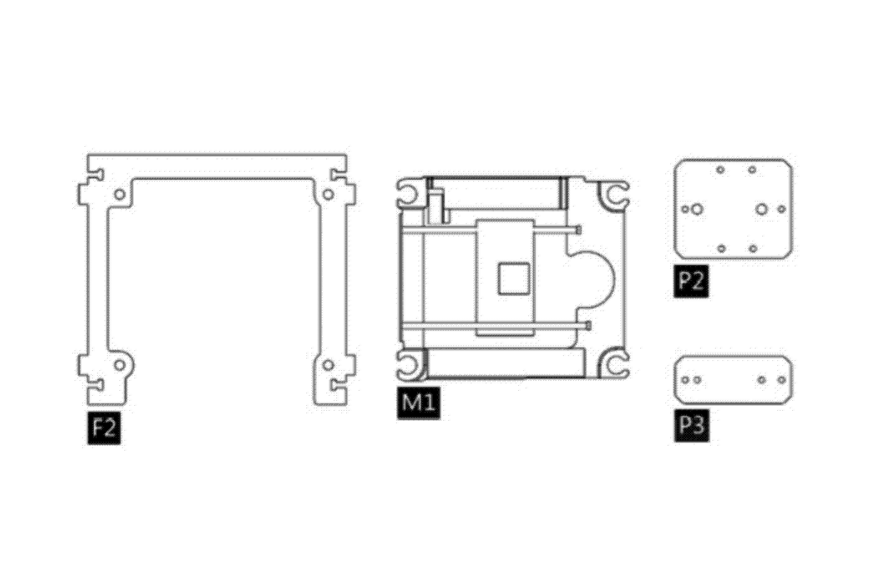
M1 × 1 F2 × 1 P2 × 1 P3 × 1 P5 (pre-installed)
X-axis parts laid out flat — M1 motor board and F2 bracket
02
Attach motor board to X-axis bracket
M1 + F2 — 4× S1 + 4× N1

Insert 4× M5 square nuts (N1) into the T-slots on F2. Position the motor board M1 against F2, aligning the four mounting holes. Insert 4× M5×10 bolts (S1) and tighten with the 4 mm hex key.
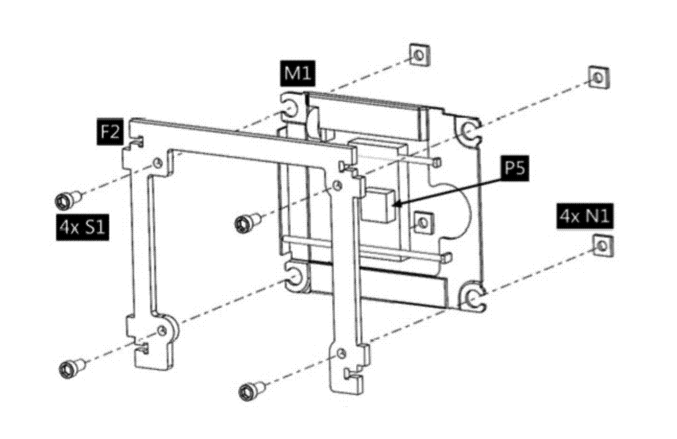
M1 × 1 F2 × 1 S1 × 4 N1 × 4
💡 Tighten bolts in a diagonal (cross) pattern to keep M1 flat against F2.
Motor board M1 bolted to X-axis bracket F2
03
Attach laser positioning plates
P3 + P4 to M1 — 2× S2 + 2× N2

Slide P3 and one loose P4 plate onto the motor carriage of M1, sandwiching the carriage. Insert 2× M3×30 bolts (S2) through P3 and P4, and thread on 2× M3 nuts (N2) by hand. Before final tightening, confirm P3 and P4 are parallel to each other.
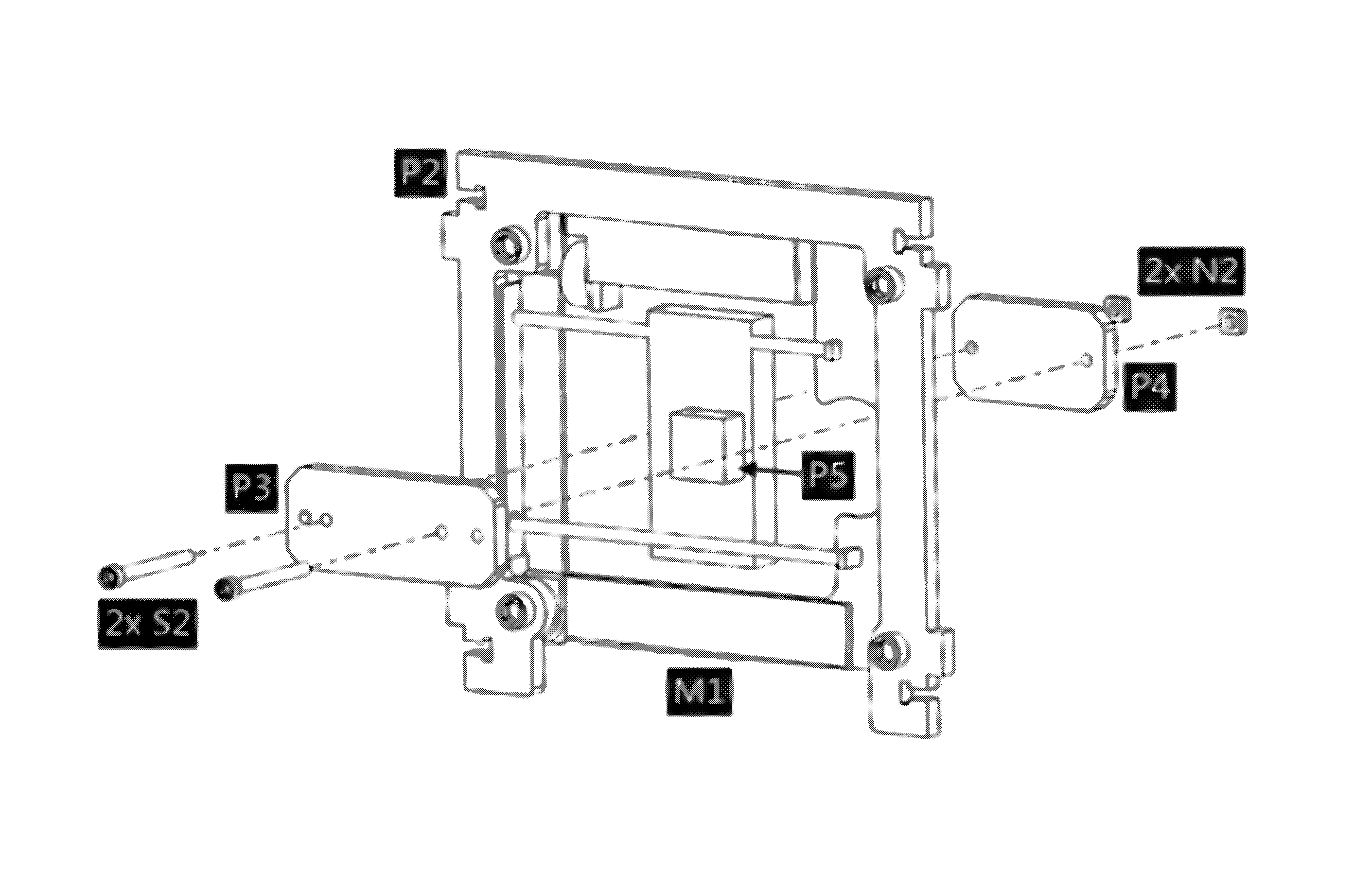
P3 × 1 P4 × 1 S2 × 2 N2 × 2
⚠️ Alternate tightening: Tighten each bolt a little at a time, alternating between the two. Over-tightening one side first can warp or crack the acrylic plates.
P3 and P4 positioning plates on X carriage with S2 bolts inserted
04
Check: verify part orientation
Front-view reference

Before continuing, compare your assembly to the front view shown. Confirm the following:
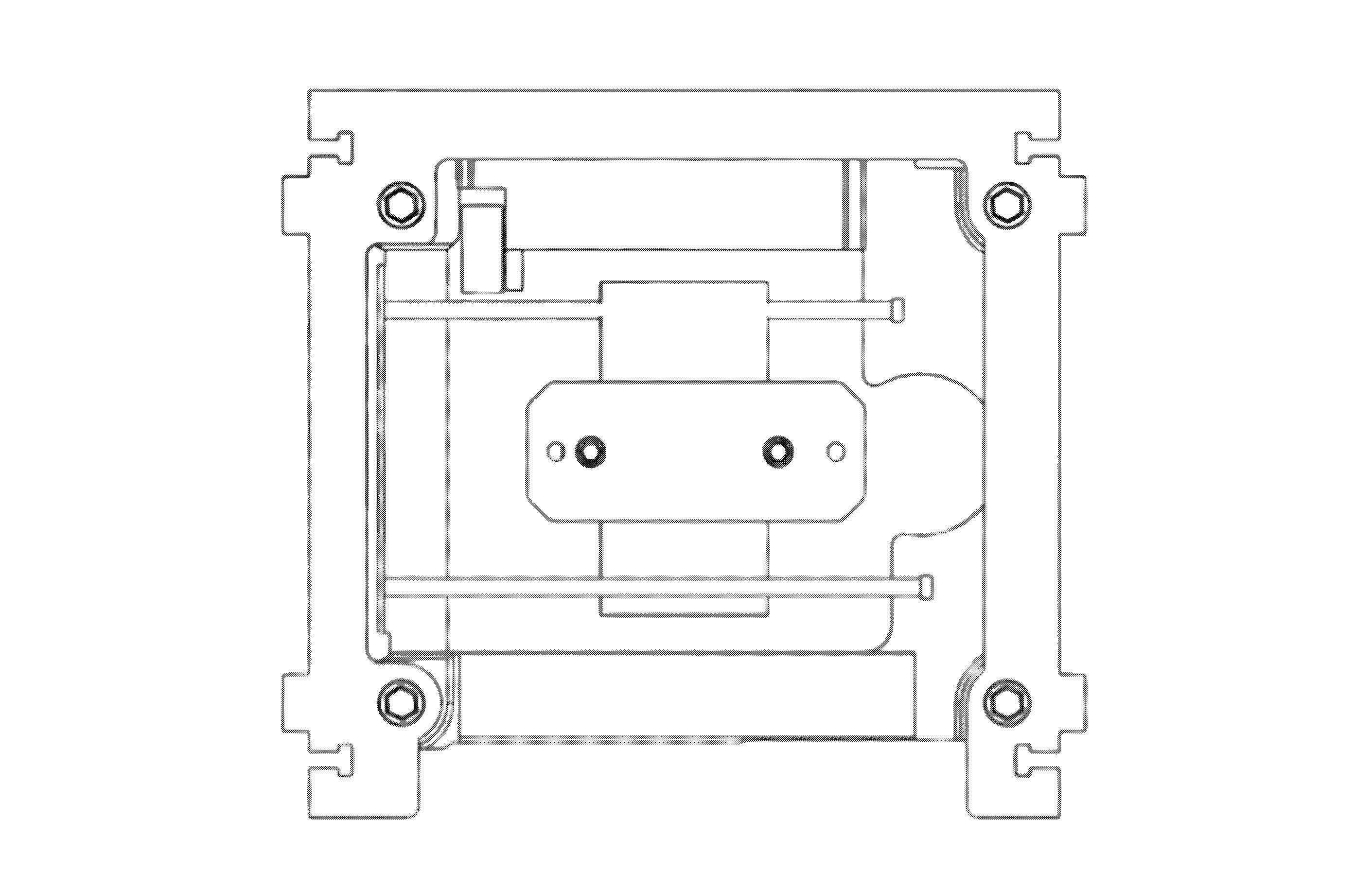
  • Motor board M1 is flush against bracket F2 with no gap
  • Plates P3 and P4 are parallel to each other — not tilted
  • The motor cable exits toward the inside of the machine (facing rear)
  • All bolts are snug — no loose movement in the carriage
⚠️ If anything looks misaligned, loosen the bolts and realign now — it is much harder to correct after the frame is closed.
Front view of X-axis carriage after steps 01–03, showing correct part orientation
05
Mount laser module to mount plate
L1 + heat sink to P2 — 4× S3

Attach the laser module L1 (with heat sink) to the laser mount plate P2 using 4× M3×12 bolts (S3) and the 2.5 mm hex key. The focus ring of the laser should face downward (toward the agar plate when installed).
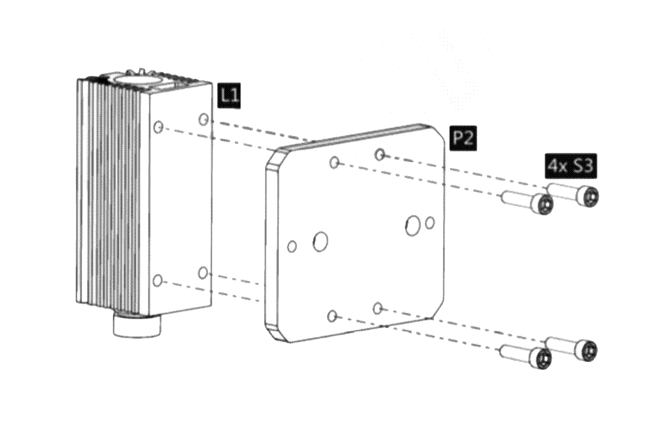
L1 × 1 P2 × 1 S3 × 4
⚠️ Do not power the machine while the laser cable is unconnected. Keep goggles nearby — you will connect the laser cable in Phase D.
Laser module and heat sink bolted to mount plate P2
06
Attach laser assembly to X carriage
P2 to M1 — 2× S3 + 2× N2

Place the laser mount plate P2 (with L1 attached) onto the front of the X motor carriage M1, aligning with the holes in P3. Insert 2× M3×12 bolts (S3) and thread on 2× M3 nuts (N2). Tighten with the 2.5 mm hex key. The X-axis carriage sub-assembly is now complete.
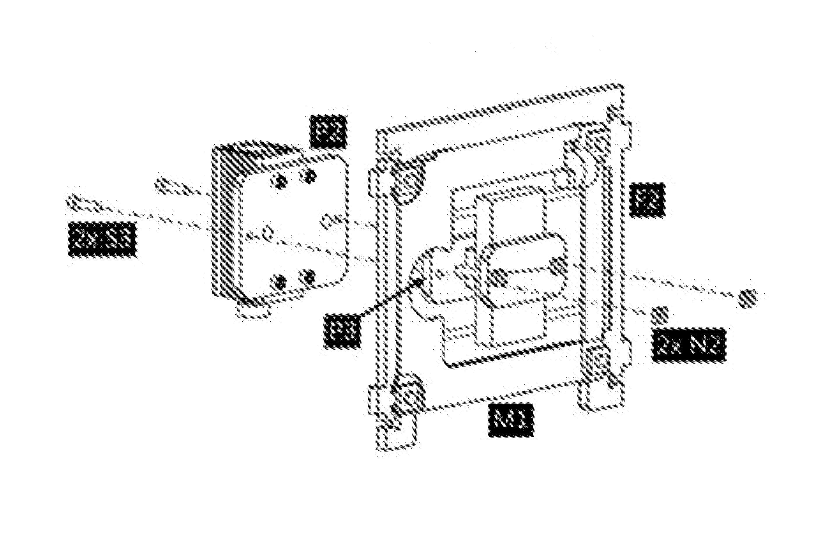
P2+L1 (from Step 5) S3 × 2 N2 × 2
💡 Set the completed X-axis carriage aside. It will attach to the side panels (F1) in Phase C.
Completed X-axis carriage
Phase B

Y-Axis carriage

The Y-axis carriage moves the agar growth platform forward and back. Assembly mirrors the X-axis, with the growth platform P1 instead of the laser.

Orientation note: Use the rear view as your reference for Y-axis orientation. The motor cable connector should face outward (toward the back of the machine).
07
Orient Y-axis parts
Identification

Identify the second stepper motor board M1, Y-axis bracket plate F3, growth platform P1, and one loose P4 positioning plate. Note that P1 already has one P5 glued to its underside — do not attempt to remove it.
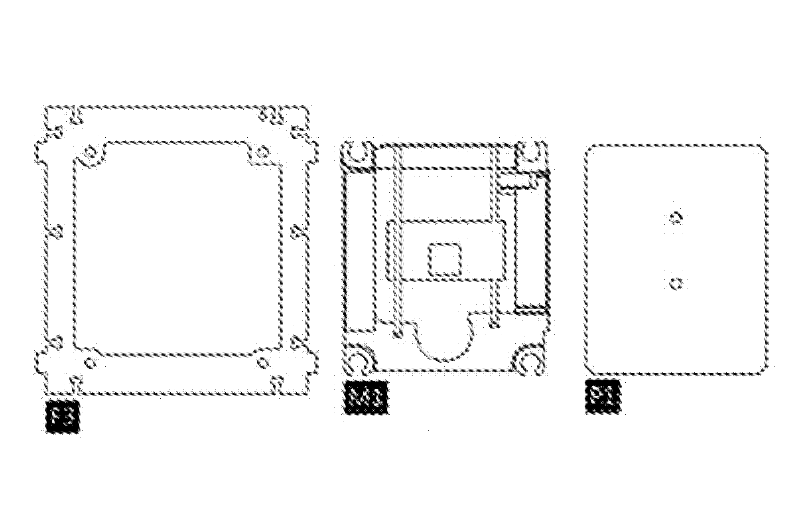
M1 × 1 F3 × 1 P1 × 1 P4 × 1 (loose)
Y-axis parts laid out flat — M1 motor board and F3 bracket
08
Attach motor board to Y-axis bracket
M1 + F3 — 4× S1 + 4× N1

Insert 4× M5 square nuts (N1) into the T-slots on F3. Align the second motor board M1 to F3 and secure with 4× M5×10 bolts (S1) using the 4 mm hex key. Tighten in a cross pattern.
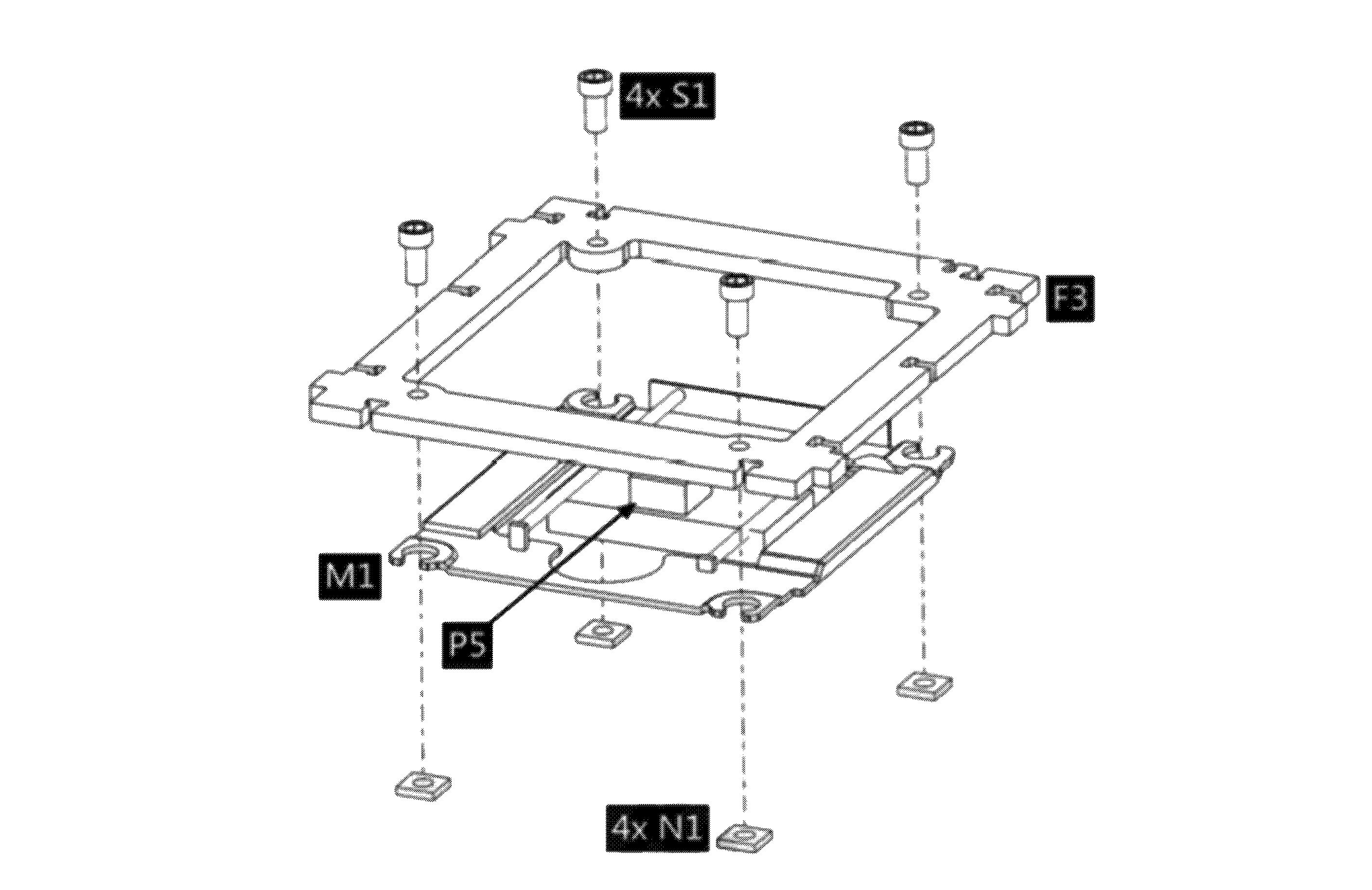
M1 × 1 F3 × 1 S1 × 4 N1 × 4
Motor board M1 bolted to Y-axis bracket F3
09
Check: verify Y-axis orientation
Rear-view reference

Before mounting the growth platform, compare your assembly to the rear view shown. Confirm the following:
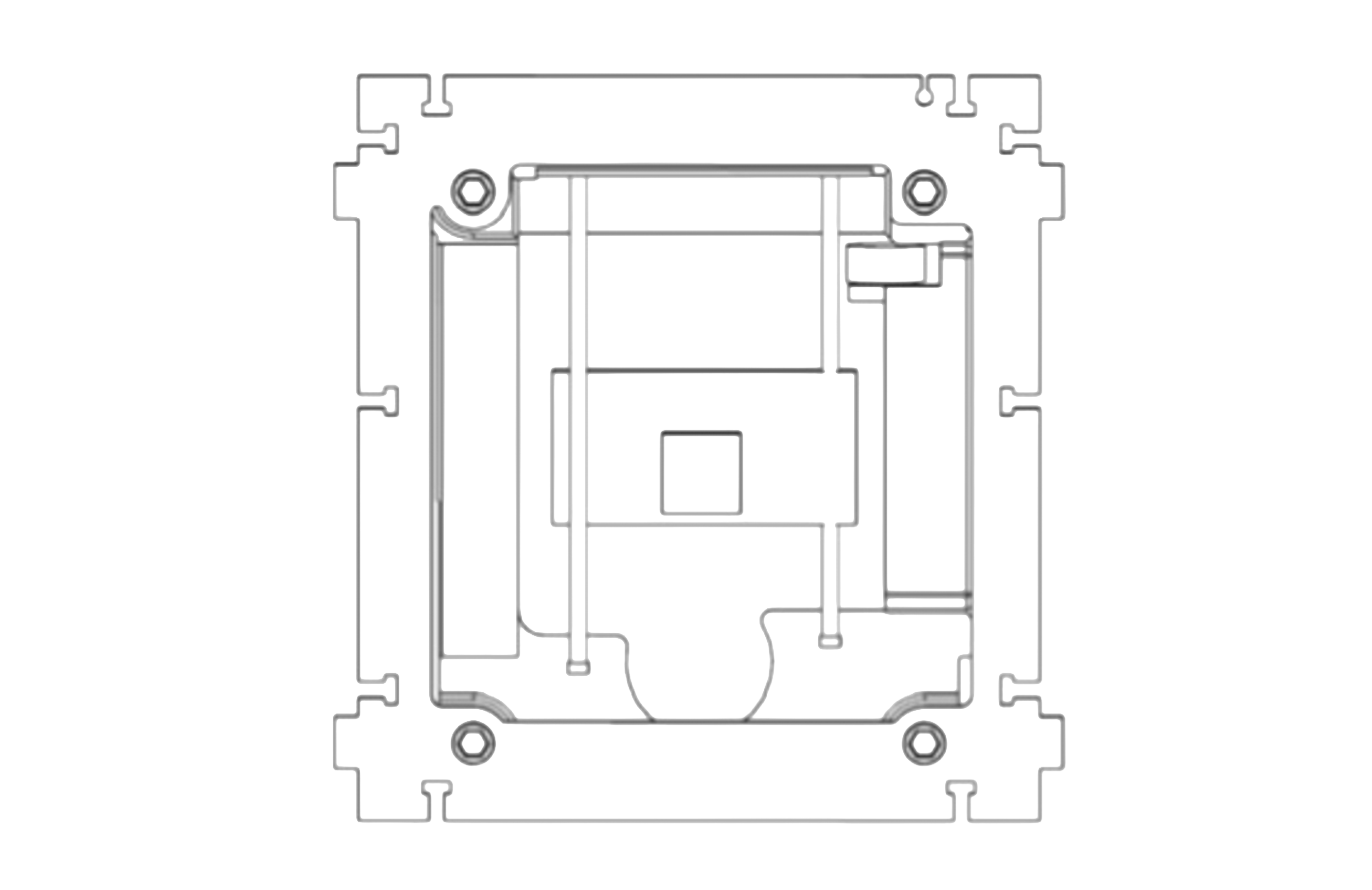
  • Motor board M1 is flush against bracket F3 with no gap
  • The motor cable exits toward the outside of the machine (facing rear)
  • The carriage slides smoothly along the rail with no binding
  • All four M5 bolts are snug
⚠️ The Y-axis orientation is the mirror of the X-axis — the cable direction is reversed. Double-check before continuing.
Rear view of Y-axis carriage after steps 07–08, showing correct part orientation
10
Mount growth platform to Y carriage
P1 + P4 to M1 — 2× S2 + 2× N2

Slide the growth platform P1 (with its pre-glued P5) onto the Y motor carriage, then place the loose P4 on the opposite side. Insert 2× M3×30 bolts (S2) through both P4 plates and secure with 2× M3 nuts (N2). Alternate tightening — keep P1 perfectly level.
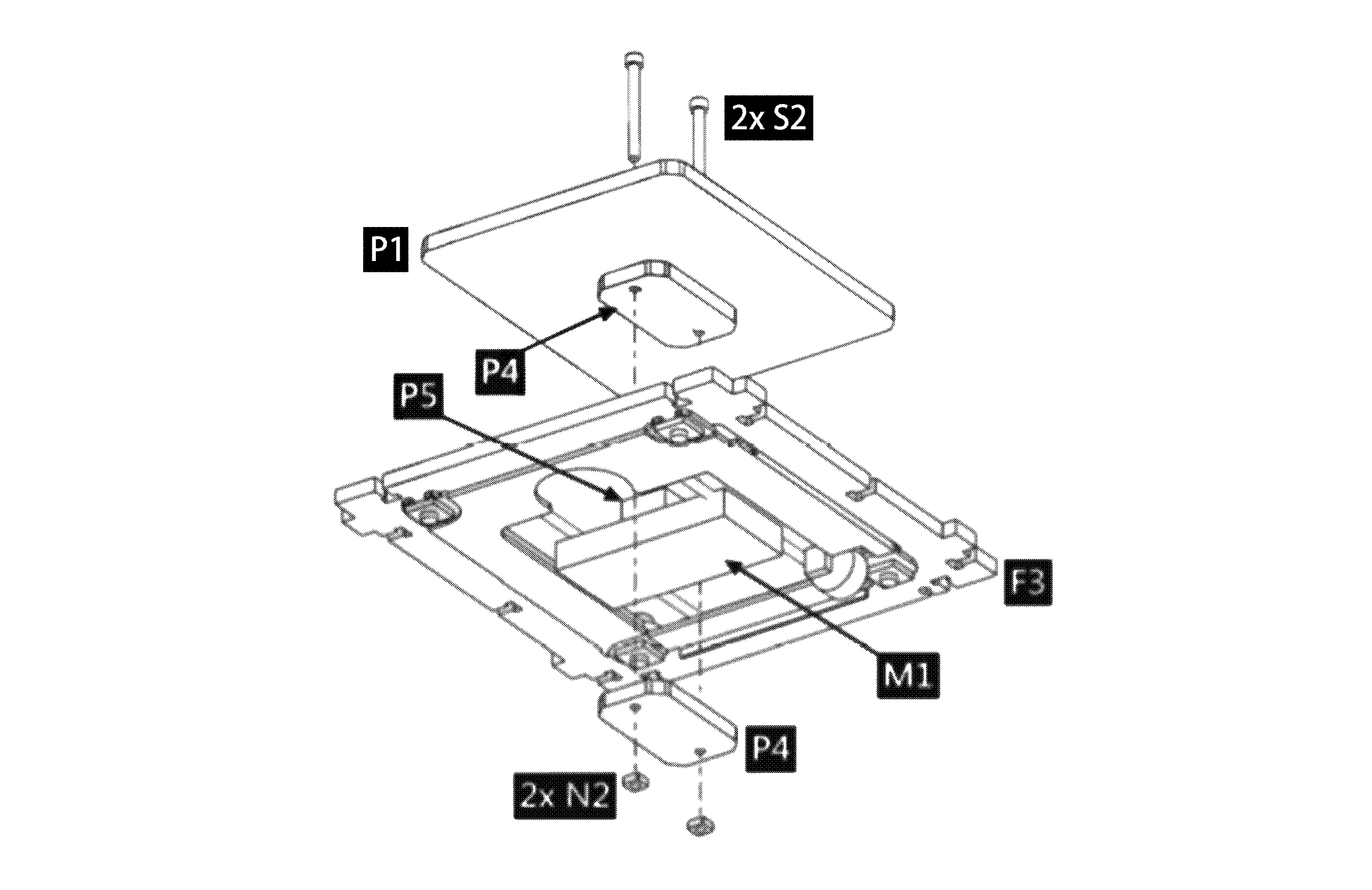
P1 × 1 P4 × 1 (loose) S2 × 2 N2 × 2
⚠️ Alternate tightening is critical here. The growth platform must be level — a tilted platform will cause uneven contact with the agar plate and inconsistent fungal growth patterns.
Growth platform P1 mounted on Y carriage with P4 plates parallel
11
✓ Check — Y-axis complete
Before proceeding to frame assembly

Verify the Y-axis sub-assembly before moving on: growth platform is level, both P4 plates are flush, bolts snug but not over-torqued.
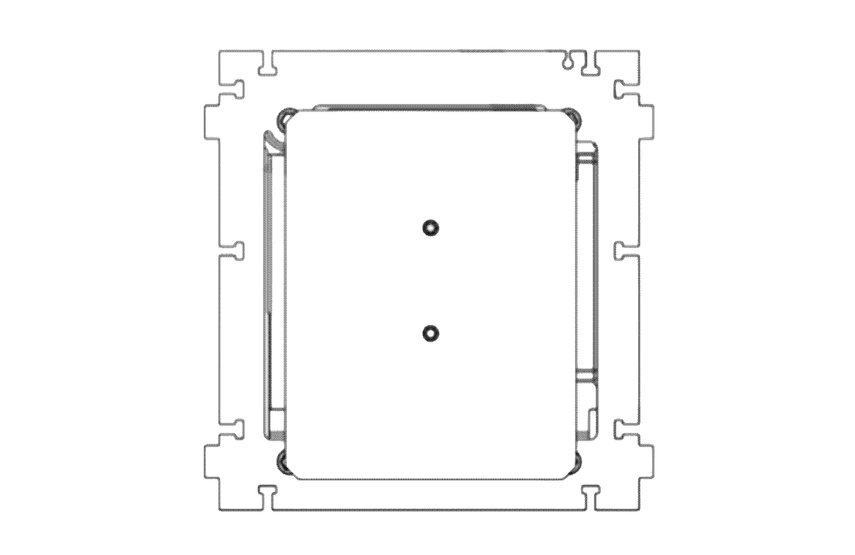
Y-axis sub-assembly complete — top view showing level platform
Phase C

Frame assembly

Join both carriage sub-assemblies into the acrylic frame. Work on a clean, stable surface — the panels slot together precisely.

12
Mount X & Y assemblies to first side panel
F2 + F3 to F1 — 5× S3 + 5× N2

Stand one side panel F1 upright. Slot the X-axis bracket F2 (from Phase A) and Y-axis bracket F3 (from Phase B) into the notches on F1. Secure with 5× M3×12 bolts (S3) and 5× M3 nuts (N2) using the 2.5 mm hex key.
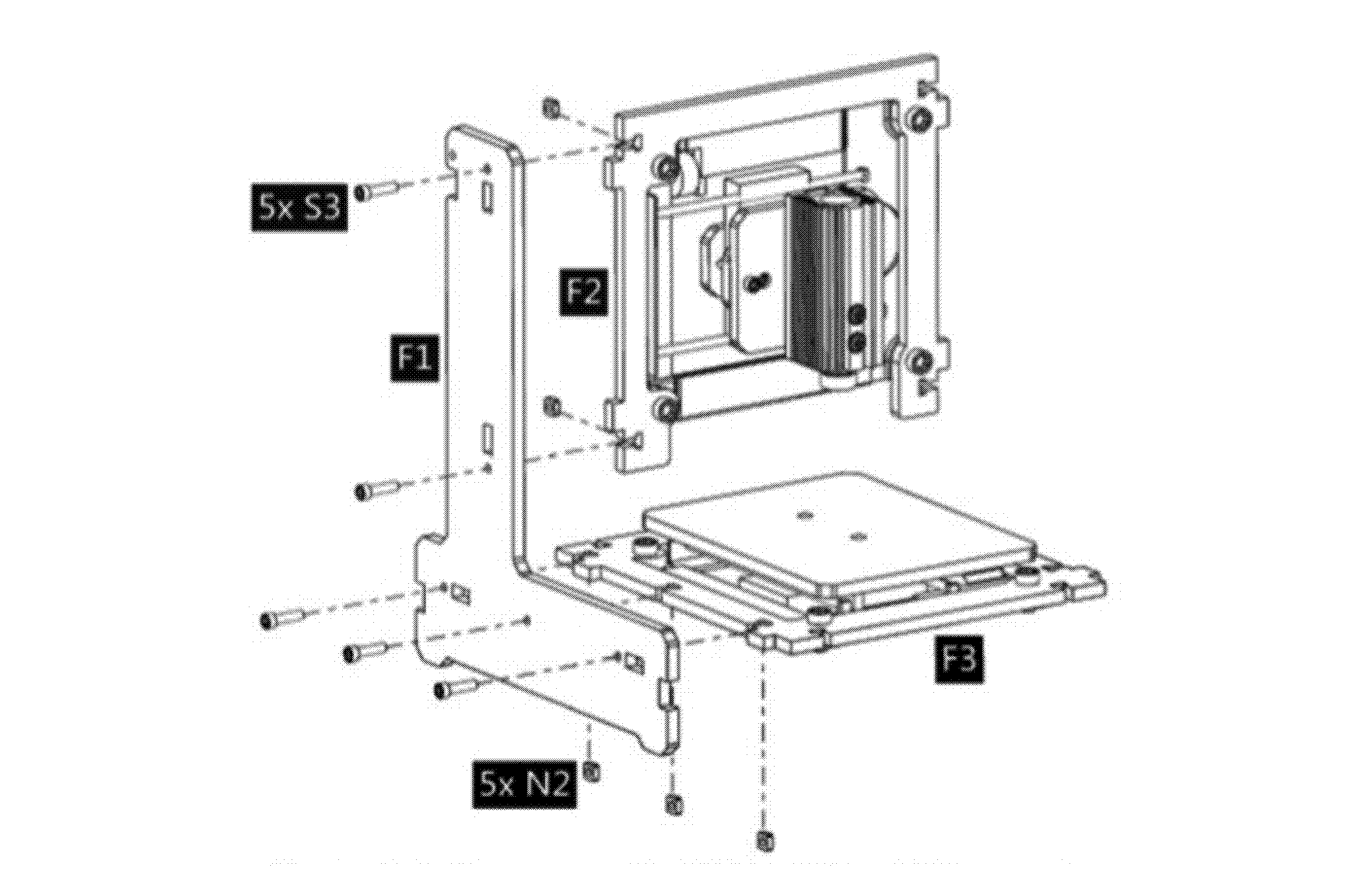
F1 × 1 F2+M1 assembly F3+M1 assembly S3 × 5 N2 × 5
X and Y assemblies slotted into first side panel F1
13
Attach second side panel
F1 × 2nd — 5× S3 + 5× N2

Slot the second side panel F1 onto the open ends of F2 and F3. Secure with 5× M3×12 bolts (S3) and 5× M3 nuts (N2). The frame should now feel rigid — check that all four corners are flush before continuing.
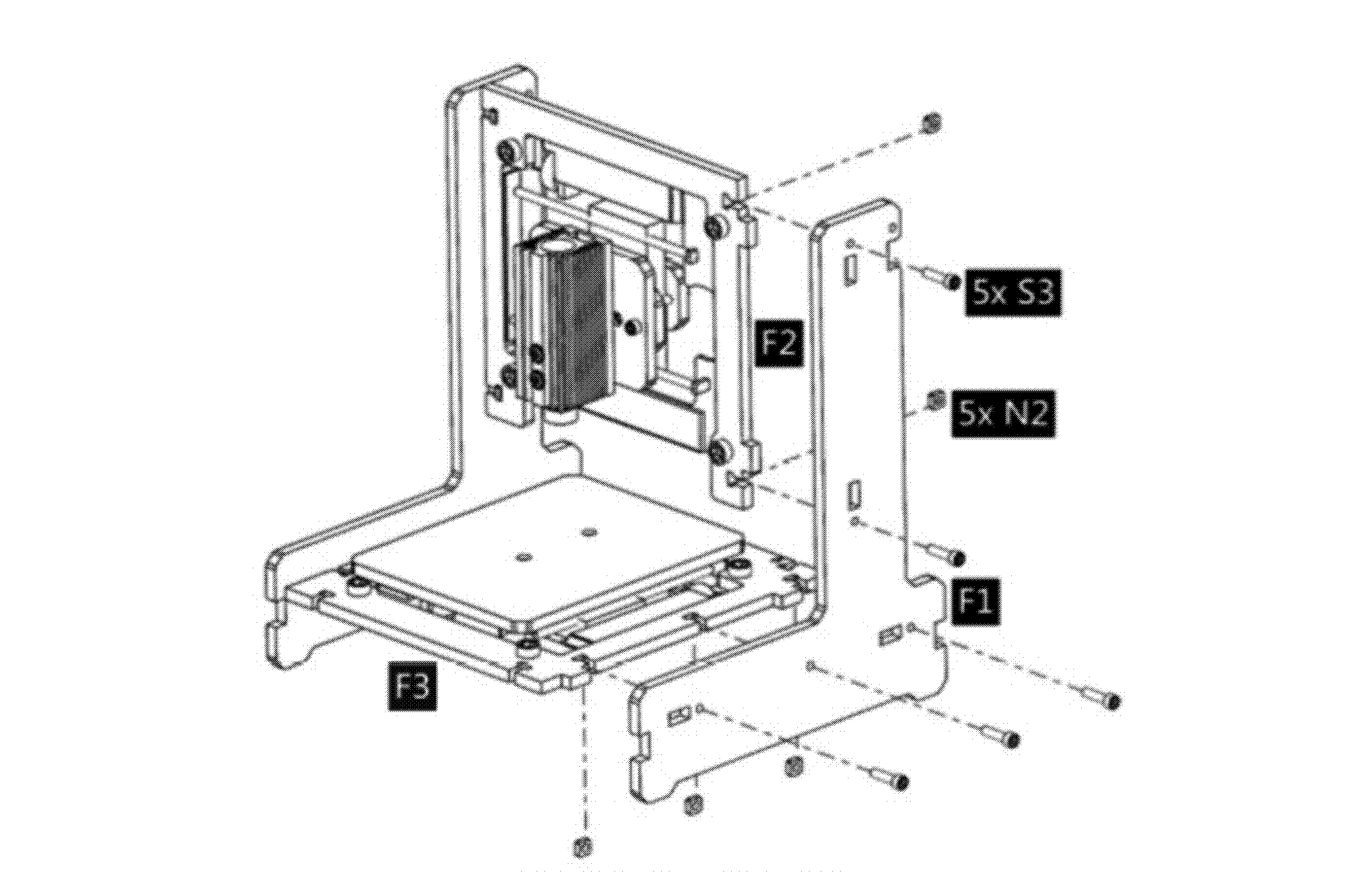
F1 × 1 (2nd panel) S3 × 5 N2 × 5
Both side panels F1 attached, frame standing
14
Prepare electronics mount plate
C1 to F6 — 4× N3 + 4× S3 + 4× N2

Place the control board C1 onto the electronics mount plate F6. Insert a 2 mm washer (N3) under each of the four mounting holes as standoffs to protect the board, then secure with 4× M3×12 bolts (S3) and 4× M3 nuts (N2).
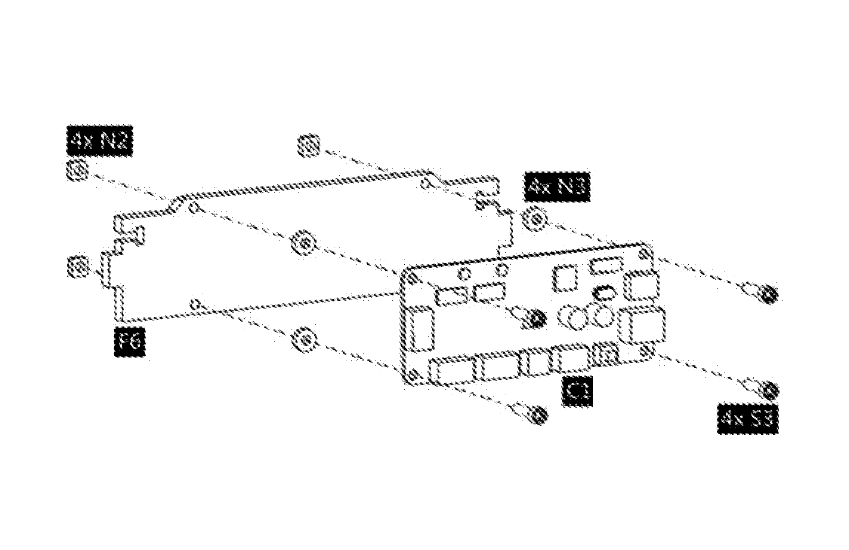
C1 × 1 F6 × 1 N3 × 4 S3 × 4 N2 × 4
💡 The N3 washers act as standoffs — they create a 2 mm air gap between the control board and the acrylic plate, preventing short circuits.
Control board C1 mounted on electronics plate F6 with washers
15
Install electronics plate into frame
F6 into frame — 2× S3 + 2× N2

Slide the F6+C1 assembly into the rear slot of the frame (between the two F1 side panels). Secure with 2× M3×12 bolts (S3) and 2× M3 nuts (N2).
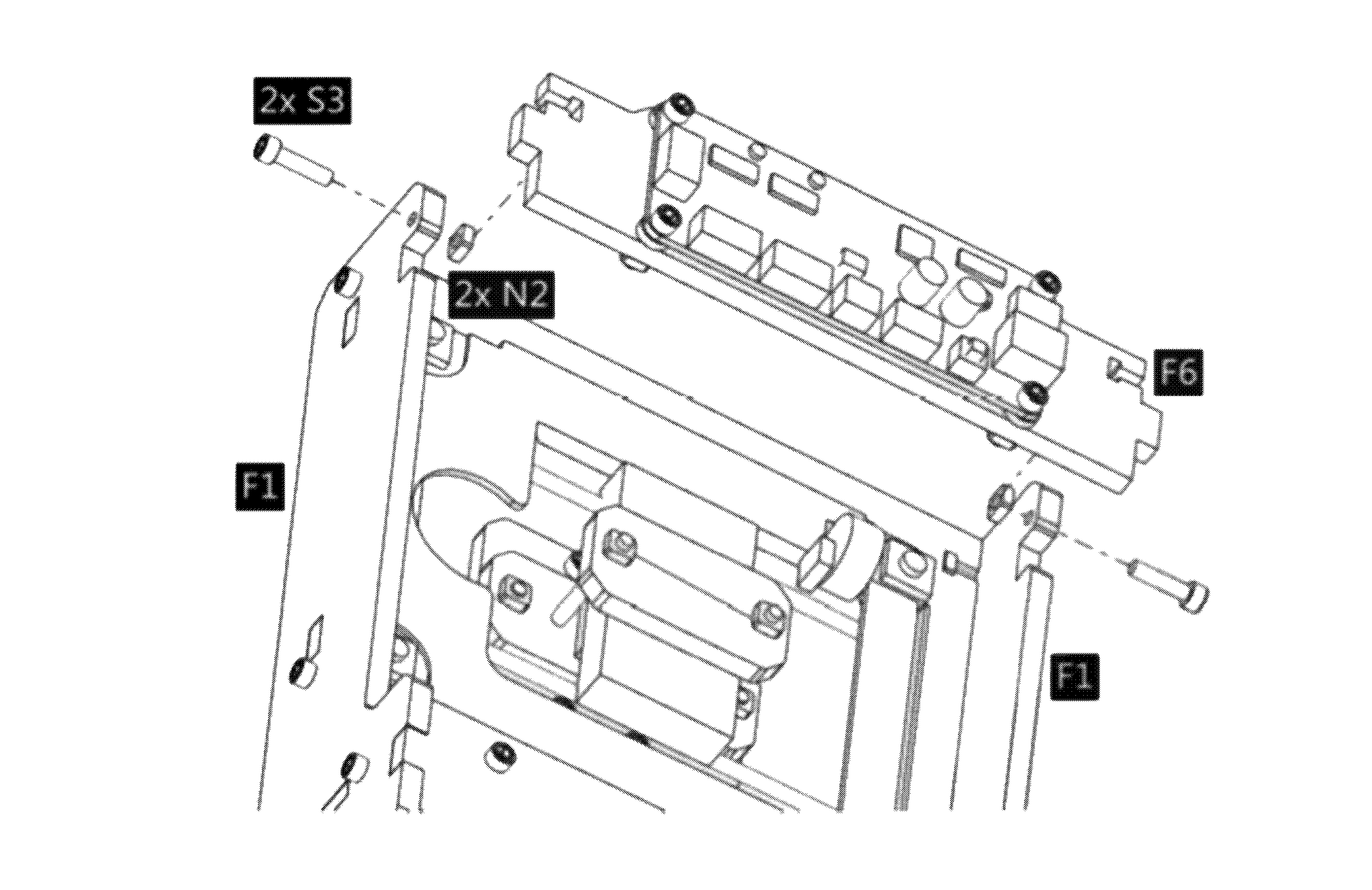
F6+C1 assembly S3 × 2 N2 × 2
Electronics plate F6 installed into rear of frame
16
Route Y motor cable & attach back panel
F5 — 2× S3 + 2× N2

Before installing the back panel, locate the Y-axis motor cable. Thread it upward through the small cable hole on F3 — this is important, otherwise the cable will be trapped and you will need to disassemble. Then attach the back panel F5 and secure with 2× S3 + 2× N2.
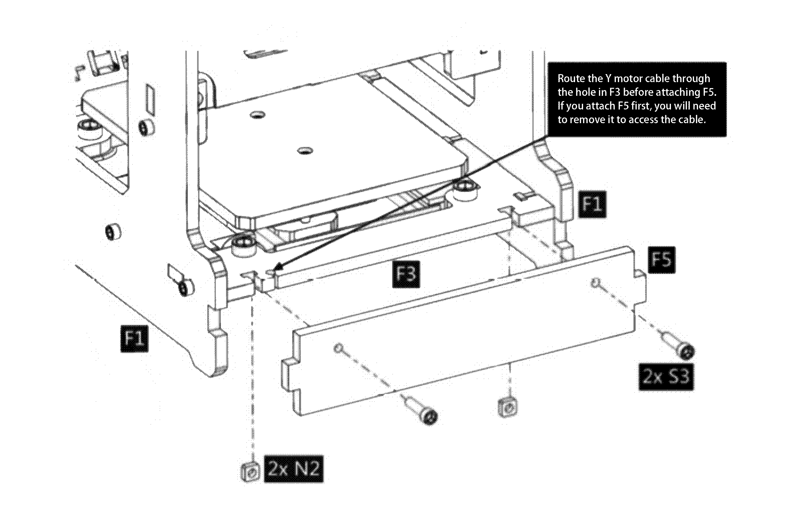
F5 × 1 S3 × 2 N2 × 2
⚠️ Thread the cable first. Route the Y motor cable through the hole in F3 before attaching F5. If you attach F5 first, you will need to remove it to access the cable.
Y motor cable routed through F3, rear panel F5 installed
17
Attach front panel
F4 — 2× S3 + 2× N2

Slot the front panel F4 into the front of the frame and secure with 2× M3×12 bolts (S3) and 2× M3 nuts (N2). The mechanical assembly is now complete.
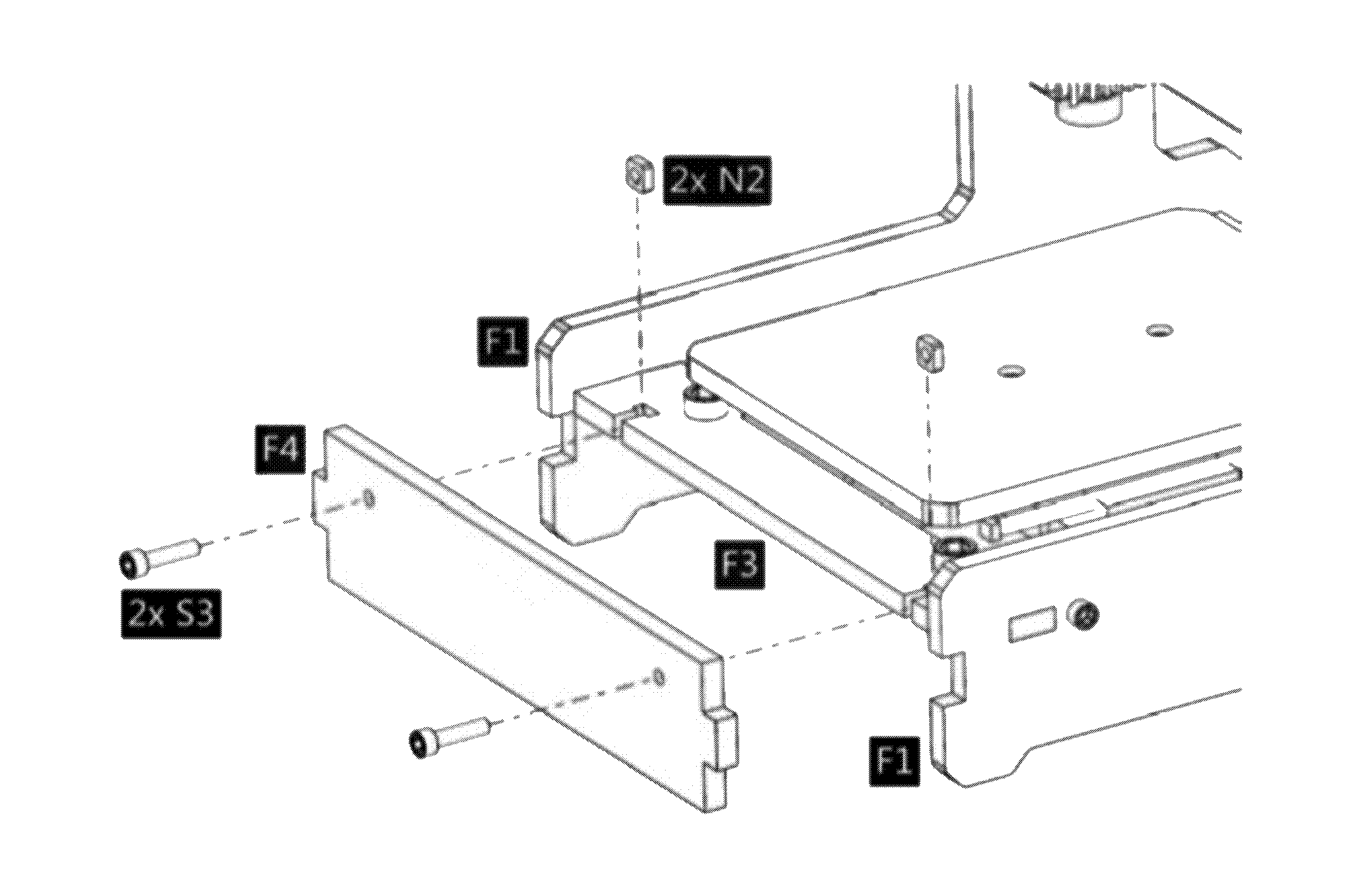
F4 × 1 S3 × 2 N2 × 2
💡 Stand back and verify the machine looks like the product photos. Both motor carriages should move smoothly by hand — slide them to check for any binding before continuing.
Completed frame with all panels installed
18
✓ Frame complete — well done!
Mechanical assembly finished

Your Mycelian Micro frame is fully assembled. Take a moment to check that all panels are flush, all bolts are snug, and both carriages slide freely. You're ready to move on to electronics and wiring.
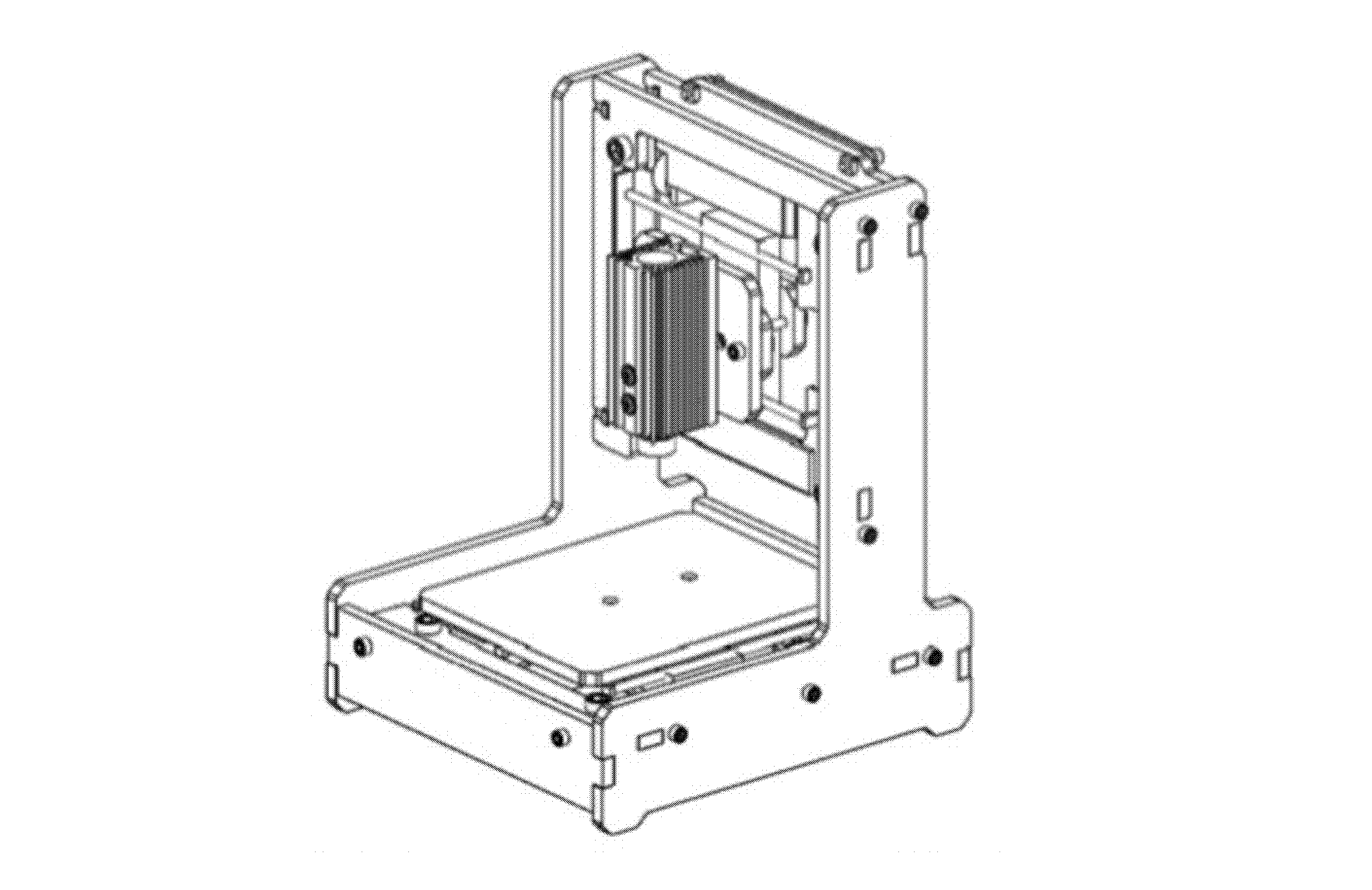
Fully assembled Mycelian Micro frame
Safety

Pre-use safety checklist

Before connecting power and using the laser, confirm each item below. Tick every box to unlock the next phase.

0 / 8 confirmed
Phase D

Electronics & wiring

Connect the motors, laser, and power to the control board. Double-check each connector before powering on.

⚠️
Do not connect power yet. Complete all wiring connections with the machine unplugged. Only plug in the 12 V adapter at Step 18.

Control board connector map

Y Motor

The single Y-motor port on the left edge of the board.

X Motor

The single X-motor port. The 4-pin JST connector fits one way only — do not force it.

Laser (PWM)

3-pin laser port labeled PWM / GND / 12 V. Connect the laser module cable here.

12 V DC Input

Barrel jack on the right edge of the board. Connect the included power adapter last.

USB

USB-B port on the right edge. Connect to your computer using the included USB cable.
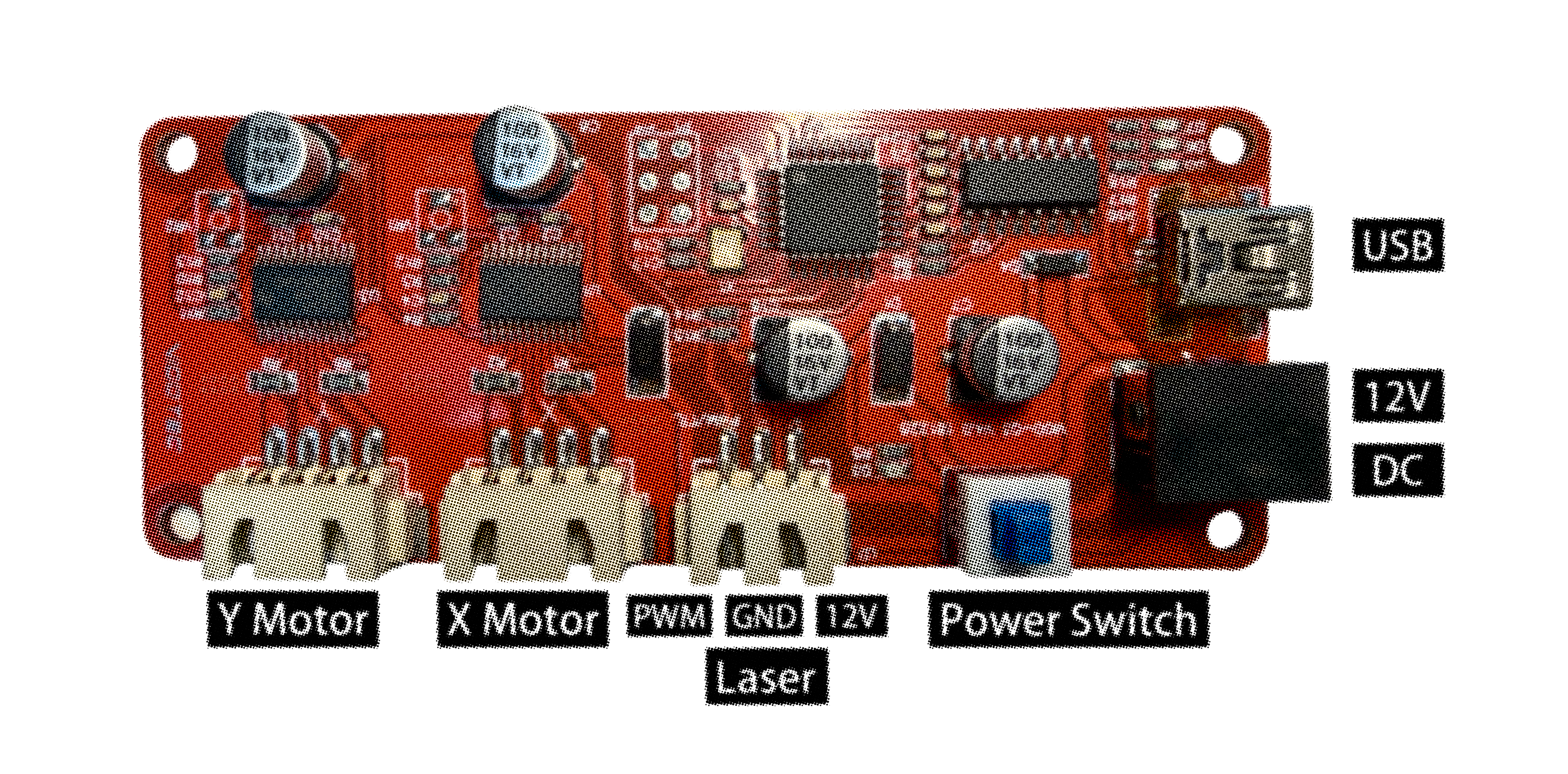
Control board connector diagram — Y Motor, X Motor, Laser (PWM/GND/12V), Power Switch, 12V DC, USB
Control board — connector reference for all wiring steps
19
Connect motor cables
4-pin JST connectors

Connect the X-axis motor cable (from the Phase A carriage) to the X Motor port on C1. Connect the Y-axis motor cable (routed through F3 in Step 16) to the Y Motor port on C1.

20
Connect laser module cable
3-pin PWM port

Connect the laser module cable to the Laser (PWM/GND/12V) port on the control board. The connector is keyed — align the notch before pressing firmly.

⚠️ Put on your goggles now. Once the laser cable is connected and power is supplied, the laser can emit light. Keep goggles on for all remaining steps.
21
Connect USB cable to computer
USB-A to USB-B

Plug the USB-B end of the data cable into the USB port on the control board. Plug the USB-A end into your computer. You will connect the software in Phase E.

22
Connect power and switch on
12 V DC barrel jack

Confirm your goggles are on. Plug the 12 V DC adapter into the barrel jack on the control board, then into the wall. Press the power switch on the control board. The power LED should illuminate.

🔌 The included adapter has a US / CN plug. If you are in Europe, the UK, Australia, or another region, you will need a local plug adapter — the adapter itself is universal voltage (100–240 V) and will work with any wall outlet once the plug fits.
Phase E

Focus calibration & first use

Set the laser focal distance and run your first boundary trace. The default software parameters are pre-configured for Mycelian Micro — do not change them unless instructed.

23
Open the web app and connect
funguylab.com/mycelian-app

In Chrome or Edge, go to funguylab.com/mycelian-app. Select the Printer Control page from the menu. Click Connect via USB in the top bar. A browser dialog will appear listing available serial ports — select the one that corresponds to your Mycelian Micro (typically labeled "USB Serial" or "CH340"). Click Connect. The status indicator will turn green and show Connected.
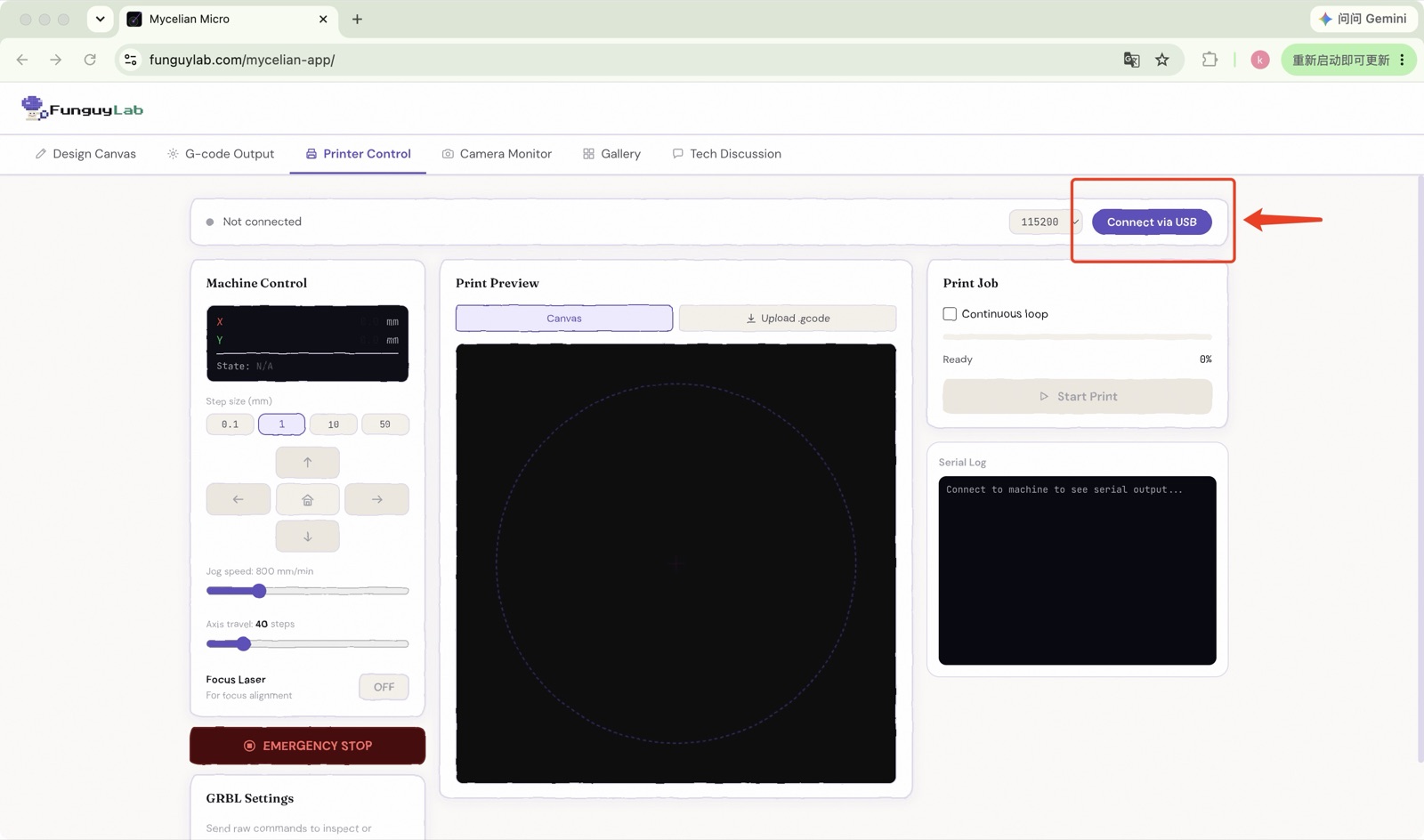
⚠️ If no port appears in the list, check that the USB cable is fully seated and the control board power LED is on. Try a different USB port on your computer if needed.
Mycelian Micro web app — Printer Control page, Connect via USB
24
Enable dim light mode
Focus adjustment

In the Mycelian Micro web app, open the Printer Control page and enable the low-power beam with the Focus Laser button at the bottom-left — toggle it from OFF to ON. The laser will emit a very low-power beam, and a faint spot should appear on the growth platform surface.
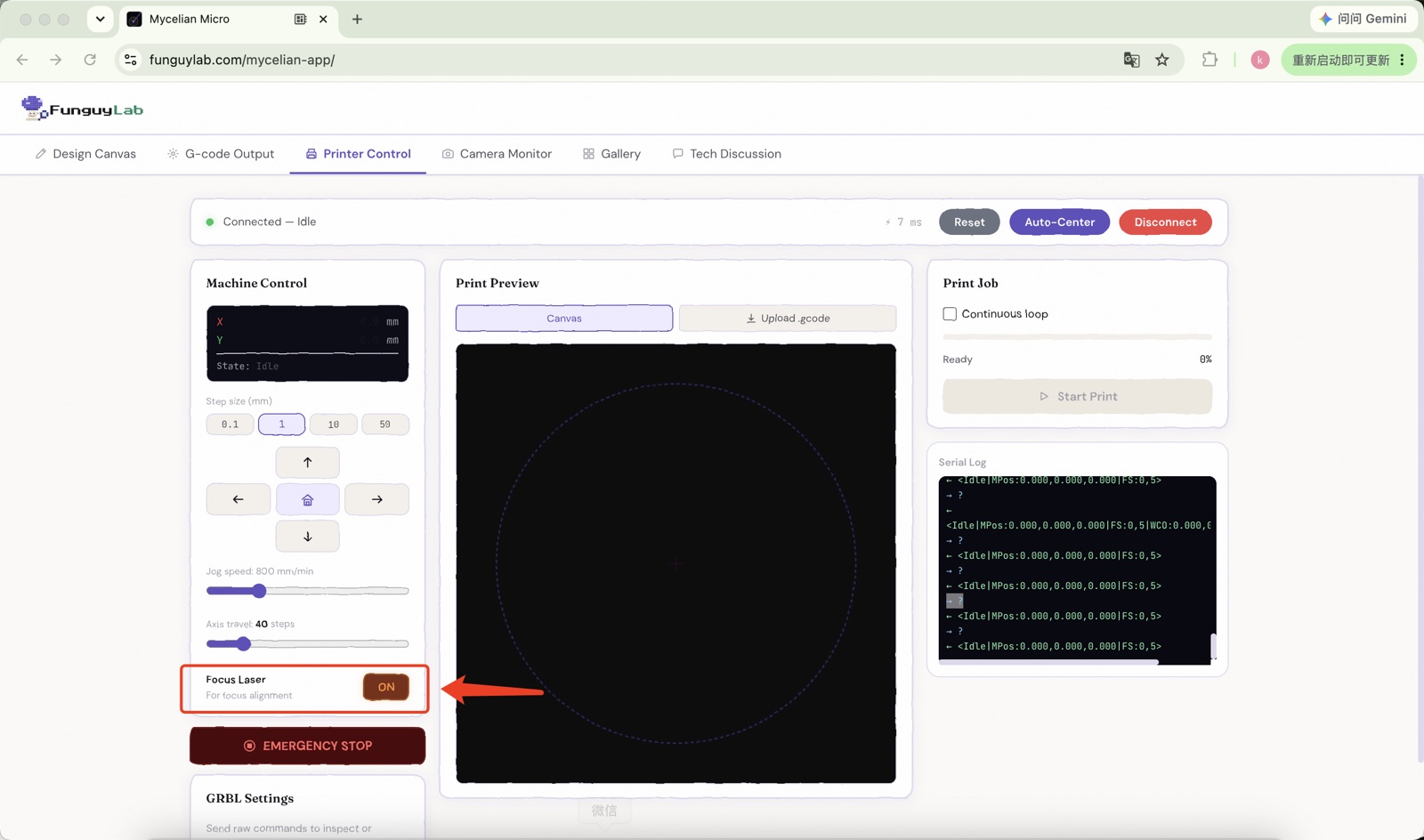
⚠️ Goggles must be on before activating dim light. The software will ask you to confirm eye protection before the laser activates.
Mycelian Micro web app — dim light enabled with the Focus Laser toggle
25
Adjust focus ring
Sharpest, smallest spot

Slowly rotate the focus ring on the laser module body — turn it back and forth while watching the spot on the growth platform surface. Stop when the spot is at its smallest and sharpest. This is the optimal focal point for your setup. Once set, turn off dim light by clicking the button again.

💡 If you cannot get a sharp spot with the focus ring alone, adjust the height of the laser module: loosen the tightening screws on the heat sink, slide the module up or down to change its distance from the platform, then re-tighten and fine-tune with the focus ring.
Phase F

Software & first print

Design your pattern, prepare and inoculate the agar plate, mount it on the print bed, then start your first laser trace.

💡
The web app uses WebSerial — it requires Chrome or Edge (version 89+). Safari and Firefox are not supported. If you see a "browser not supported" message, switch to Chrome.
26
Draw or import your design
Design Canvas page

Switch to the Design Canvas page. Use the shape tools (rectangle, circle, spiral, freehand) to draw directly on the print area, or click Upload SVG to import an existing vector file. The dashed square on the canvas represents the boundary of the print area (38 × 38 mm) — keep your design inside it. Use Transform to resize, rotate, or reposition shapes.
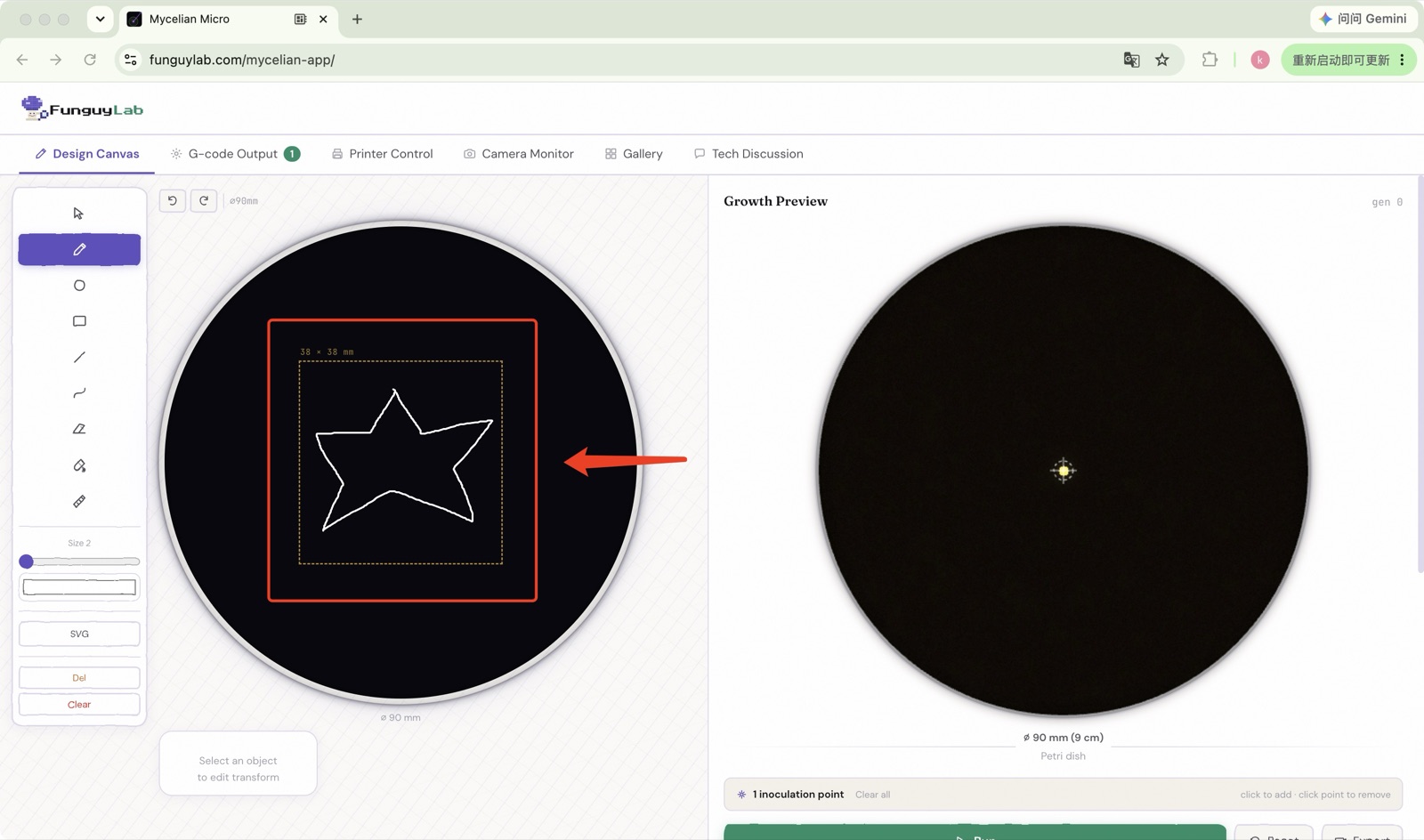
💡 For your first print, try a simple closed shape — a circle or rectangle — so you can clearly see the growth boundary after 24–48 hours.
Mycelian Micro web app — Design Canvas with a shape drawn inside the 38×38 mm print area, Growth Preview at right
27
Simulate the print
Simulator · preview growth

On the right, use the simulator to preview your print before running it. Place the fungal inoculation points — choose where and how many spots to seed on the plate — then click Run to simulate how the growth will fill your design. Adjust the design or the inoculation points and re-run until you are happy with both, then continue to the next step.
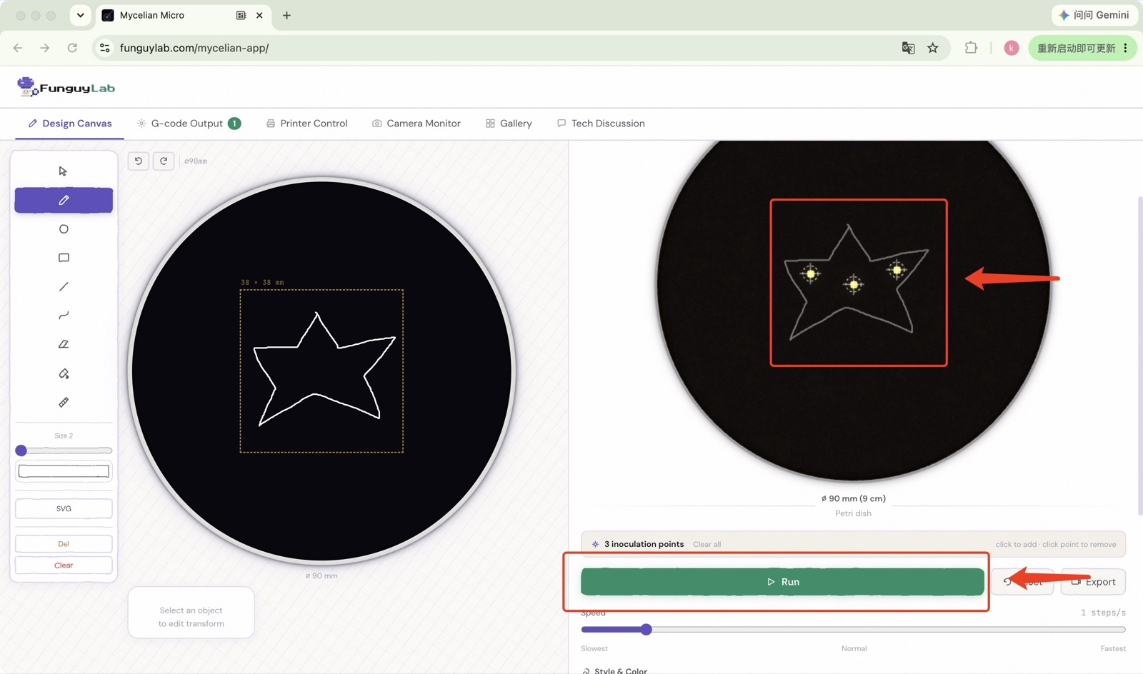
🧫
The simulator currently supports Mucor only.
Mycelian Micro web app — simulator previewing growth from placed inoculation points
28
Set print parameters
Speed · Power

On the Gcode Output page, confirm the two print parameters. The defaults are pre-configured for Mycelian Micro on standard agar — only adjust if you have a specific reason to.
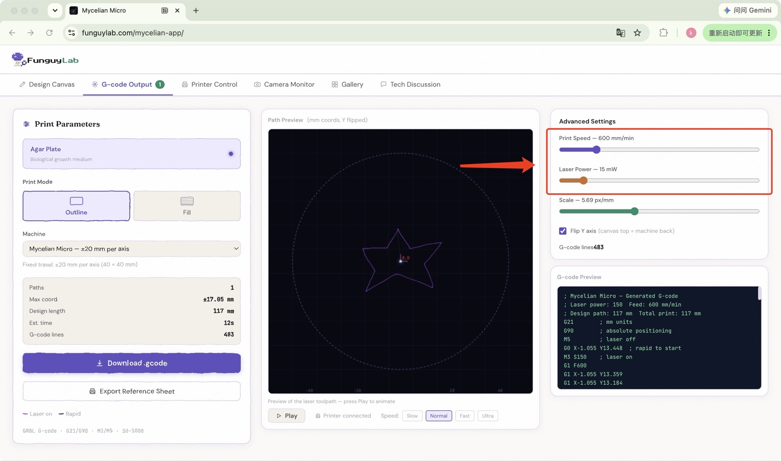
Speed — how fast the carriage moves. Lower speed = more laser exposure per mm. Default is recommended for agar.
🔆
Laser power — percentage of maximum power. Too high will gouge the agar; the default leaves a clean surface mark.
Mycelian Micro web app — Gcode Output page showing speed and laser power parameters
29
Export the reference sheet
Physical reference sheet

Click Export Reference Sheet in the web app (A4 size by default). This outputs a paper sheet showing your design at actual size, including the inoculation point markers. Print it on a standard printer and set it aside — you will attach it to the agar plate in the next step.
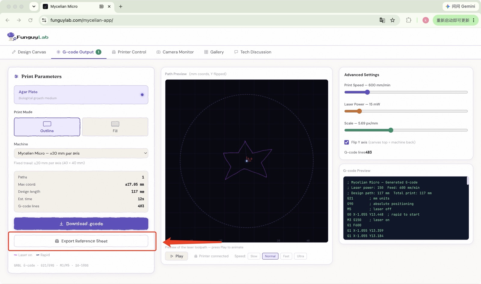
Mycelian Micro web app — Export Reference Sheet at A4 size
30
Cut template and attach to agar plate bottom
Alignment reference

Cut out the circular template along the outer boundary line. Turn the sealed agar plate upside down (lid still on). Center the template against the plate base and attach it with a small piece of tape.

31
Apply transparent circular sticker
From the kit

Peel the transparent circular sticker from the kit and place it over the template on the plate base, sticky side down. Press firmly around the edges. The sticker protects the template and will be used to fix the plate to the print bed.

32
Inoculate at template marker points
Sterile technique

Flip the plate right-side up. Open the lid and, using an inoculation loop, inoculate the agar at the marked points visible through the base. Work quickly to minimize exposure. Replace the lid immediately after inoculation.

⚠️ Work in a clean environment. Flame or use a sterile disposable loop for each inoculation point to avoid cross-contamination.
33
Mount agar plate on print bed
Sticker side down

Place the agar plate (lid facing up) onto the growth platform P1, sticker side down. Press gently so the sticker adheres to the platform surface — this keeps the plate from shifting during the print. The plate should sit flat; if it rocks, check that P1 is level (revisit Step 8).

34
Verify focus with dim light
Confirm spot is sharp on the agar

Remove the petri-dish lid so the beam falls directly onto the agar, then enable Dim Light mode again. The laser spot should land directly on the agar surface — check that it is still sharp and small. If the spot is blurry, re-adjust the focus ring (Step 25) with the plate in position. Turn off dim light when done.

⚠️ Goggles on before activating dim light.
35
Run a frame trace
Verify placement before printing

On the Gcode Output page, press the play button in the Path Preview. The machine will trace the rectangular bounding box of your design at very low laser power — just enough to show the laser position without marking the agar. Watch that the trace stays within the plate area. If it goes out of bounds, reposition the agar plate on the printer bed and trace again — do not modify your design.
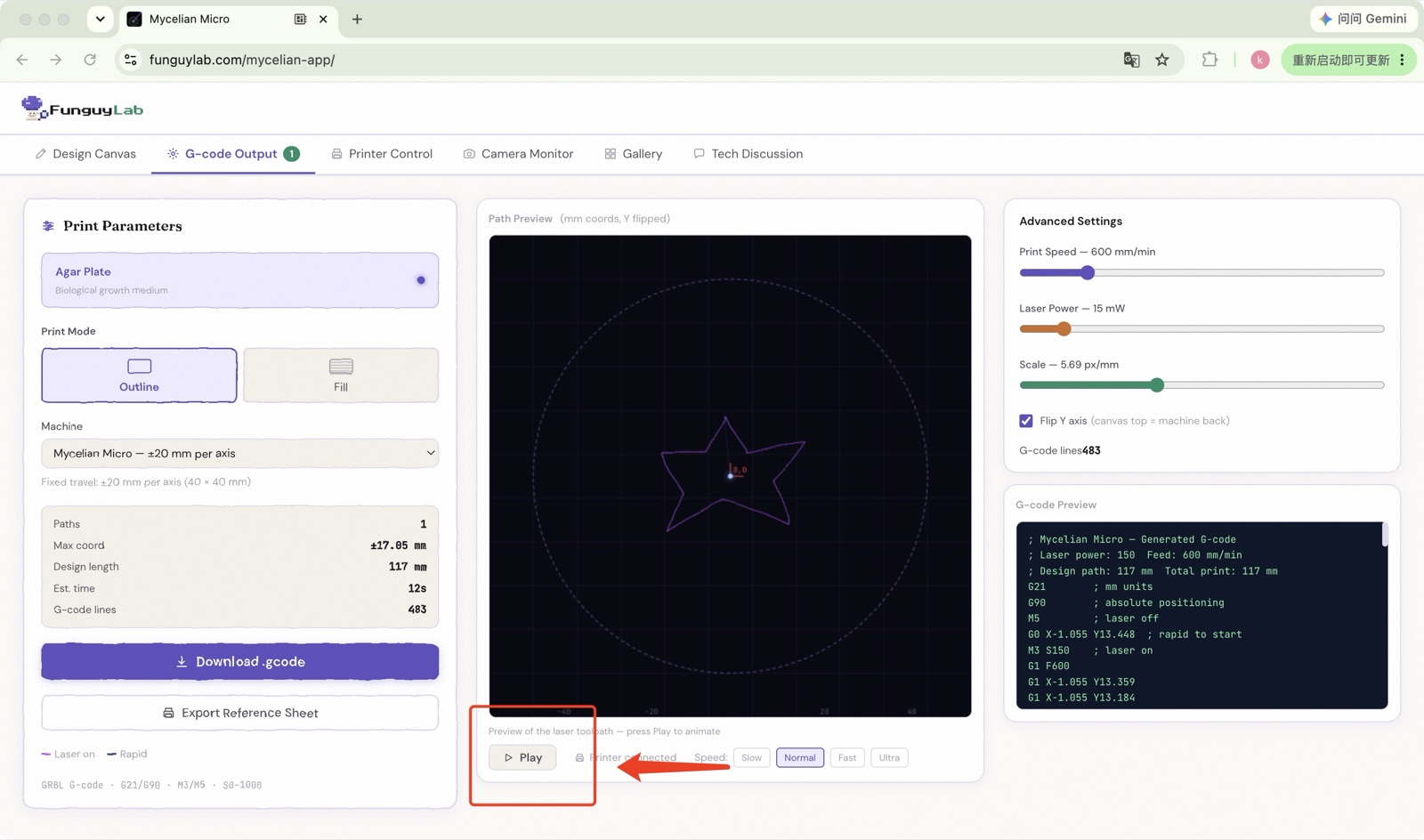
⚠️ Goggles on before running any trace. The laser is active during the frame trace even at low power.
Mycelian Micro web app — Path Preview running a frame trace
36
Start your first print
Continuous loop · machine lid closed

On the Printer Control page, under Print Job, select Continuous Loop so the machine re-traces your design over and over, steadily guiding growth over the agar, then click Start Print. With the petri-dish lid off, the machine traces your design directly onto the agar surface at the power you set, and you can set a custom run duration. When the job finishes the machine returns to its home position automatically. Keep the machine's enclosure lid closed for the entire print.
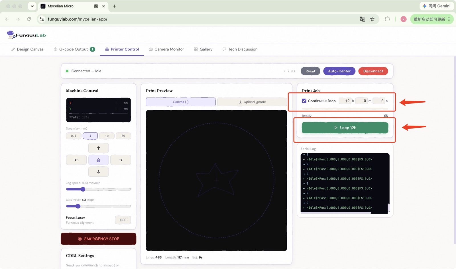
⚠️ Do not lean over the machine while the laser is running. Keep the room well-ventilated.
⏱️ How long to run. For Mucor, we recommend a continuous loop of 24 hours or more. Slime molds grow faster and can use a shorter run.
🧫 Take the petri-dish lid off during printing. A closed dish lid can fog with condensation or refract the beam. To keep the agar from drying out or getting contaminated while it's uncovered, protect the plate with our Mini Isolation Grow Chamber (sold separately) — or any clean cover if you don't have one.
💡 After printing, place the plate in a warm dark spot. For Mucor, signs of growth usually appear from around 12 hours, and the mycelium typically fills the agar within 24–48 hours.
Mycelian Micro web app — Start Print with a continuous-loop print job
🍄

Assembly complete.

Your Mycelian Micro is ready. Open the web app, load your design, inoculate with your Mucor culture, and start your first growth trace. Results are typically visible within 24–48 hours.

Start your first project → Safety reference
Troubleshooting

Common issues

Software won't detect the machine

Check USB cable is fully seated. Confirm the control board power LED is on. Restart the software and click Connect again. Compatible with Windows 7/8/10/11 and macOS 10.13+.

Laser spot is large / blurry

Adjust the focus ring (Step 21). Ensure agar plate is within 5–10 cm of the laser output. Check that P1 is level and not tilted.

Carriage moves unevenly or jerks

Loosen and re-tighten the motor board bolts (Steps 2 and 7). Check that no acrylic chips or debris are caught in the rails. Verify motor cables are fully seated.

Growth pattern doesn't match design

Re-check focus (Step 21). Verify the agar plate was inoculated after (not during) tracing. Ensure plate was kept at room temperature 22–26 °C for at least 24 h.

Still stuck? Email support@funguylab.com — include a photo and we'll help you sort it.